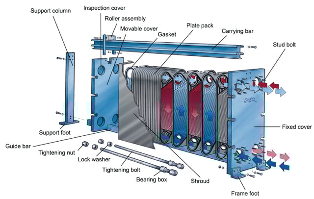
In a gasketed plate heat exchanger, the plates are fitted with elastomeric gaskets which seal the channels and direct the fluids into alternate channels. The plate pack is assembled between a frame plate and a pressure plate, and compressed by tightening bolts fitted between these plates. The channel plates and the pressure plate are suspended from an upper carrying bar and located by a lower guiding bar, both of which are fixed to the support column. The physical design of the gasketed plate heat exchanger allows easy cleaning, and modification of capacity by the addition or removal of plates.
This animation above shows the working principle of an Alfa Laval liquid/liquid 1-pass gasketed plate-and-frame heat exchanger where the fluids run counter-currently through the heat exchanger. The hot liquid (illustrated in red) normally enters through one of the upper connections and leaves through the connection underneath. The cold liquid (illustrated in blue) enters through one of the lower connections and leaves through the connection above.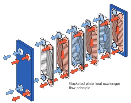
As the fluids pass through the heat exchanger, heat is transferred from the hot media to the cold media. Counter current flow enables maximum heat recovery possibilities and very close temperature approach can be achieved. Temperature cross is also possible, meaning that the hot outlet can reach a lower temperature than the cold outlet. This can only be achieved to a limited extent with tubular heat exchangers making plate-and-frame heat exchangers more thermally efficient. You can learn more about the benefits of GPHEs vs shell-and-tube heat exchangers by clicking here.
The fluids enter through the connections and portholes of the heat transfer plates. Specially designed sealing gaskets located between the plates direct the fluids so that the hot and cold fluids pass counter-currently in alternating channels. When the fluid enters between the plates, it passes over the distribution area. Alfa Laval offers two types of distribution areas: our patented CurveFlowTM and the chocolate pattern. The distribution area is one of the most important features of a plate heat exchanger. Its main purpose is to ensure an even flow of fluid over the entire plate while maximizing heat transfer efficiency and minimizing maldistribution and fouling. In the animation you can see that the distribution area helps the fluids to quickly fill up the entire cross section of the plates.
For very heat sensitive media, co-current flow is used in gasketed plate-and-frame heat exchangers. The benefit with this design is that the coldest fluid meets the hottest fluid when entering the heat exchanger, minimizing the risk of overheating or freezing sensitive media. In the animation you can imagine that the hot fluid is reversed, so that both fluids are entering at the bottom connections.
The animation shows the working principle of a conventional gasketed plate-and-frame heat exchanger, but the same working principle is applicable also to specialized ranges such as our Semi-welded and WideGap plate heat exchangers.
Alfa Laval has an extremely broad range of gasketed plate-and-frame heat exchangers which are used in all types of industries. The number of sizes, plate and gasket materials and available options are enormous.
The animation above shows the working principle of an Alfa Laval gasketed plate-and-frame heat exchanger when used as a steam heater. The steam or vapour (illustrated in grey) enters through one of the upper connections and the condensate leaves through the connection underneath. The cold liquid (illustrated in blue transferring into red) enters through one of the lower connections and leaves through the connection above.
As the fluids pass through the heat exchanger heat is transferred from the condensing steam/vapour to the cold media. The fluids enter through the connections and port holes of the heat transfer plates. Specially designed sealing gaskets located between the plates direct the fluids so that the hot and cold fluids pass counter-currently in alternating channels. When the fluid enters between the plates, it passes over the distribution area. Alfa Laval offers two types of distribution areas: our patented CurveFlowTM and the chocolate pattern. The distribution area is one of the most important features of a plate heat exchanger. Its main purpose is to ensure an even flow of fluid over the entire plate while maximizing heat transfer efficiency and minimizing maldistribution and fouling. In the animation you can see that the distribution area helps the fluids to quickly fill up the entire cross section of the plates.
The animation shows the working principle of a conventional gasketed plate-and-frame heat exchanger, but the same working principle is applicable also to specialized ranges such as our Semi-welded and WideGap plate heat exchangers.
The animation above shows the working principle of an Alfa Laval liquid/liquid 2-pass gasketed plate-and- frame heat exchanger where the fluids run counter-currently through the heat exchanger. The turning plate in the middle of the plate pack directs the flow into the two passes. The hot liquid (illustrated in red) enters through one of the connections in the frame plate. The fluid runs through the heat exchanger in two passes and then leaves through one of the connections in the pressure plate. The cold liquid (illustrated in blue) simultaneously enters through one of the connections in the pressure plate and leaves through one the connections in the frame plate.
As the fluids pass through the heat exchanger, heat is transferred from the hot media to the cold media. Countercurrent flow enables maximum heat recovery possibilities and very close temperature approach can be achieved. Temperature cross is also possible, meaning that the hot outlet can reach a lower temperature than the cold outlet. This can only be achieved to a limited extent with tubular heat exchangers making plate-and-frame heat exchangers more thermally efficient. You can learn more about the benefits of GPHEs vs shell-and-tube heat exchangers by clicking here.
The fluids enter through the connections and portholes of the heat transfer plates. Specially designed sealing gaskets located between the plates direct the fluids so that the hot and cold fluids pass counter-currently in alternating channels. When the fluid enters between the plates, it passes over the distribution area. Alfa Laval offers two types of distribution areas: our patented CurveFlow and the chocolate pattern. The distribution area is one of the most important features of a plate heat exchanger. Its main purpose is to ensure an even flow of fluid over the entire plate while maximizing heat transfer efficiency and minimizing maldistribution and fouling. In the animation you can see that the distribution area helps the fluids to quickly fill up the entire cross section of the plates.
The animation shows the flow principle of a conventional gasketed plate-and-frame heat exchanger with a 2-pass configuration, but additional passes are possible. It is also possible to have a different number of passes on each side of the heat exchanger. For bigger models with higher flow rates, reinforcing partition plates are sometimes used which are not shown in the animation. Specialized ranges of the gasketed plate-and-frame heat exchanger are also possible such as our Semi-welded and WideGap.
For very heat sensitive media, co-current flow is used in gasketed plate-and-frame heat exchangers. The benefit with this design is that the coldest fluid meets the hottest fluid when entering the heat exchanger, minimizing the risk of overheating or freezing sensitive media. In the animation, you can imagine reversing the cold fluid so that both fluids are entering at the frame plate connections.
Alfa Laval has an extremely broad range of gasketed plate-and-frame heat exchangers which are used in all types of industries. The number of sizes, plate and gasket materials and available options are enormous.
![]()