IGCC process heat transfer
Optimizing heat transfer processes at integrated gasification combined cycle plants poses challenges. To meet the specific requirements for gasification, gas shifting and gas cleaning processes, Alfa Laval offers vast expertise and a broad portfolio of equipment and services that increase reliability, energy efficiency and output while reducing costs and environmental impact.
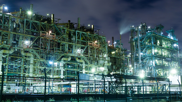
Optimizing IGCC heat transfer processes
Increasing IGCC plant output requires reliable, energy-efficient heat transfer solutions that reduce costs and environmental impact. Between the gasification, gas shifting and gas cleaning islands, an IGCC plant requires a multitude of process heat exchangers, each with its specific needs. Regardless of the need – whether high or low operating temperatures and/or pressures, special alloys or carbon steel, fouling or cleaning services, cycling or steady operation, the solution must be very reliable. Alfa Laval’s portfolio delivers the right solution for most any requirements.
Alfa Laval experts can customize shell-and-tube heat exchangers, welded plate heat exchangers, and gasketed plate heat exchangers to meet the combination of mechanical strength, corrosion resistance, process performance, and desired operating capabilities that are required for a given application.
With its straightforward, rugged design and special alloy construction, the Alfa Laval Olmi shell-and-tube heat exchanger, for instance, can withstand extreme process conditions. It delivers reliable operation at pressures of up to 450 bar and temperatures of more than 1000°C (1863°F).
Alfa Laval welded plate heat exchangers are another example of compact and efficient heat transfer for a wide range of processes that involve a wide range of media – from crude oil and bitumen to asphalt, slurry oil and sludge.
To stay competitive, IGCC plant owners and operators rely on Alfa Laval to deliver great value for the most demanding IGCC processes.
Product videos and animations
Alfa Laval Packinox installations
Process overview
![]()
1. Gasifier
The coal is gasified into a synthesis gas, the “left over” (slag) is taken away for disposal. The syngas is cooled down and transferred to the gas cleaning part of the process.
2. Gas cleaning
The cool raw syngas is introduced at the bottom of the absorption tower, where it makes contact with a solvent (selexol) that travels downwards through the tower’s packing material. CO2 is absorbed by the solvent. Rest of the gas (now cleaned) goes out through the chimney.
A. Cold solvent with the CO2 goes through the Alfa Laval Packinox heat exchanger and is heated up on its way to the stripper tower.
B. Warm solvent with CO2 goes into the top of the stripper tower and then travels downwards. Steam is introduced at the bottom of the tower and travels upwards, encountering the solvent. The heat of the steam releases the CO2.
C. A mix of steam and CO2 leaves the top of the stripper. It is later cooled down to water and CO2, where the CO2 is compressed prior to storage / injection into old oil wells.
D. The clean solvent goes back in a closed loop to the absorption tower. On its way back to the absorption tower the hot clean solvent passes through the heat exchanger and is thereby heating up the solvent (with CO2) that is on its way to the stripper tower.
E. When the clean solvent heats up the cold solvent (with CO2) it is thereby cooled down. Back in the absorption tower the clean cold solvent is used to capture more CO2.
3. Gas turbine
The clean syngas is combusted in the gas turbine to generate electricity.
4. Boiler
The flue gas from the combustion is transferred to the boiler where it is heating water to generate steam.
5. Steam turbine
The steam generates additional electricity – the majority of the electricity in the IGCC plant is generated by the steam turbine.
6. Condenser
The condenser then cools down (condenses) the steam to water which is reused for cooling the raw syngas in step one of the process. The raw syngas heats up (while cooling down) the condensate which turns into steam that goes back into the boiler for further electricity generation.
7. CO2 storage
The captured and compressed CO2 is injected into old oil wells under high pressure, thereby pushing up additional oil from the well. The CO2 remains – and is thereby stored – in the geological formation.